
Here is the standard way of creating a program with CODE: first, the user draws the graph that shows the parallel program's communication structure. Then the user annotates this graph by filling in forms that describe properties of the nodes and arcs in the graph. For example, the user must specify the sequential computation a node performs. Finally, the user runs the program, which CODE translates, compiles, and executes.

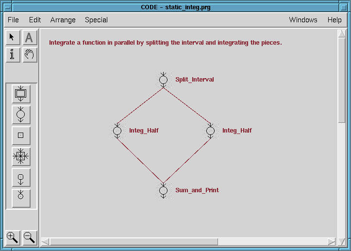
This program integrates a function over an interval by dividing the interval in half and integrating over each piece separately. The results are added to form the final answer. The program consists of four computation nodes. The arcs represent data created by one computation and needed by another. When the program runs, it first executes (or "fires") the computation node called Split_Interval which divides the interval in half and sends the endpoints of the sub-intervals to each of the Integ_Half nodes.
These nodes integrate a function over the interval they receive from Split_Interval. They can run in parallel with each other since there are no arcs between them. The node Sum_and_Print waits for the results of these two integrations and then prints their sum.

Notice that the "Start Node" option is selected. This means that this node is the first one to be executed when the program begins. There is only one start node allowed. Likewise, only one "Stop Node" is allowed, and when it fires, the program execution ends.
The sequential computation defined by this node is part of the "Specification." This specification also includes the mapping between data on the incoming and outgoing arcs and local data used by the computation, as well as conditions under which the node is allowed to fire. We will discuss the details of specifications in the next section.
 home page
 specifications
 Introduction to CODE / emery@cs.utexas.edu / Last updated 15 August 1995