Project One
Project 1: Ray Tracing
Assigned: Thursday, September 6, 2018
Due: Thursday, September 27, 2018 (by 11:59PM)
Artifact Due: Thursday, October 4, 2018 (by 11:59PM)
Project 1: Ray Tracing
Assigned: Thursday, September 6, 2018
Due: Thursday, September 27, 2018 (by 11:59PM)
Artifact Due: Thursday, October 4, 2018 (by 11:59PM)
To install the starter code, unzip the files, link a "makefile" to Makefile.campus (if that's not already done) and type "make" (or just typ e"make -f Makefile.campus). The executable resulting from a successful build generates extremely simple ray-traced images where the pixels are shaded only by the diffuse terms of the material at the ray intersections, and this only for non-polygon-mesh objects. For polygon meshes, it doesn't even compute intersections.
This project is a very large collection of files and object-oriented C++ code. Fortunately, you only need to work directly with a subset of it. However, you will probably want to spend a bit of time getting familiar with the layout and class hierarchy at first, so that when you code you know what classes and methods are available for your use.
To get started, look at comments about where to put your code in RayTracer.cpp, trimesh.cpp, light.cpp, and material.cpp. The starting point for where ray tracing begins, and where you will be needing to add a lot of functionality, is in the RayTracer.cpp file. This is a good file to start studying to explore what methods get called and what they do. In addition, the raytracer features a debugging window that allows you to see individual rays bouncing around the scene. This window provides a lot of visual feedback that can be enormously useful when debugging your application. Here is a more detailed explanation of how to use the debugging window.
The starter code can run in both text mode and gui mode. Running without any arguments will execute the program in the gui mode. For usage see 'ray --help'.
When tracing rays toward lights, you should look for intersections with objects, thereby rendering shadows. If you intersect a semi-transparent object, you should attenuate the light, thereby rendering partial (color-filtered) shadows, but you may ignore refraction of the light source.
The skeleton code doesn't implement Phong interpolation of normals. You need to add code for this (only for meshes with per-vertex normals.)
Here are some equations that will come in handy when writing your shading and ray tracing algorithms.
Most of your effort should be spent on approach 2, i.e. reducing the number of ray-object intersection tests. You are free to experiment with any of the acceleration schemes described in Chapter 6, ''A Survey of Ray Tracing Acceleration Techniques,'' of Glassner's book. Of course, you are also free to invent new acceleration methods.
Make sure that you design your acceleration module so that it is able to handle the current set of geometric primitives - that is, triangles, spheres, squares, boxes, and cones. You need not try to thread the building of any acceleration structures. They should be additional shared read-only structures as far as your rendering threads are concerned.
The sample scenes include several simple scenes and three complex test scenes: trimesh1, trimesh2, and trimesh3. You will notice that trimesh1 has per-vertex normals and materials, and trimesh2 has per-vertex materials but not normals. Per-vertex normals and materials imply interpolation of these quantities at the current ray-triangle intersection point (using barycentric coordinates).
The test scenes each contain up to thousands of triangles. A portion of your grade for this assignment will be based on the speed of your ray tracer running on these scenes. The faster you can render a picture, the higher your grade.
For grading on the rendering speed, the scenes will be traced at the specific size with one ray traced per pixel, and the rays should be traced with 5 levels of recursion, i.e. each ray should bounce 5 times. If during these bounces you strike surfaces with a zero specular reflectance and zero refraction, stop there. At each bounce, rays should be traced to all light sources, including shadow testing. The command line for testing rendering speed looks like: ray -w 400 -r 5 [in.ray] [out.bmp].
The renderer should use the default number of threads, i.e. the number supported by the hardware it is running on, when it is run from the command line with no explicit switch to override the default number of threads. Be sure to enable your acceleration structure when the program is invoked from the command line. You are welcome to precompute scene-specific (but not viewpoint-specific) acceleration structures and make other time-memory tradeoffs, but your precomputation time and memory use should be reasonable. Don't try to customize your ray tracer for the test scenes; we will also use other scenes during grading.
If you have any questions about what constitutes a fair acceleration technique, ask us. Compiling with optimization enabled (e.g. the -O3 flag in gcc) is allowed. Coding your inner loops in machine language is not allowed. Using multiple processors is not allowed. In general, don't go overboard tuning aspects of your system that aren't related to tracing rays.
Furthermore, the performance of your acceleration structure will be measured using wallclock time on one core of a CS departmental Linux machine. Therefore, your code must compile on one of the Linux machines in the GDC labs. If you need help with this, please let the TA know. Most of your code should be easily portable.
![]() Implement stochastic (jittered) supersampling. See Glassner, Chapter
5, Section 4.1 - 4.2 and the first 4 pages of Section 7.
Implement stochastic (jittered) supersampling. See Glassner, Chapter
5, Section 4.1 - 4.2 and the first 4 pages of Section 7.
![]() Deal with overlapping objects intelligently. In class, we
discussed how to handle refraction for non-overlapping objects in air.
This approach breaks down when objects intersect or are wholly
contained inside other objects. Add support to the refraction code for
detecting this and handling it in a more realistic fashion.
Note, however, that in the real world, objects can't coexist in the
same place at the same time. You will have to make assumptions as to
how to choose the index of refraction in the overlapping space. Make
those assumptions clear when demonstrating the results.
Deal with overlapping objects intelligently. In class, we
discussed how to handle refraction for non-overlapping objects in air.
This approach breaks down when objects intersect or are wholly
contained inside other objects. Add support to the refraction code for
detecting this and handling it in a more realistic fashion.
Note, however, that in the real world, objects can't coexist in the
same place at the same time. You will have to make assumptions as to
how to choose the index of refraction in the overlapping space. Make
those assumptions clear when demonstrating the results.
![]() Implement spot lights.
Implement spot lights.
![]() Implement antialiasing by adaptive supersampling, as described
in Glassner, Chapter 1, Section 4.5 and Figure 19 or in Foley, et al.,
15.10.4. For full credit, you must show some sort of visualization of
the sampling pattern that results. For example, you could create
another image where each pixel is given an intensity proportional to
the number of rays used to calculate the color of the corresponding
pixel in the ray traced image. Implementing this bell/whistle is a big
win -- nice antialiasing at low cost.
Implement antialiasing by adaptive supersampling, as described
in Glassner, Chapter 1, Section 4.5 and Figure 19 or in Foley, et al.,
15.10.4. For full credit, you must show some sort of visualization of
the sampling pattern that results. For example, you could create
another image where each pixel is given an intensity proportional to
the number of rays used to calculate the color of the corresponding
pixel in the ray traced image. Implementing this bell/whistle is a big
win -- nice antialiasing at low cost.
![]() Add some new types of geometry to the ray tracer. Consider
implementing torii or general quadrics. Many other objects are
possible here.
Add some new types of geometry to the ray tracer. Consider
implementing torii or general quadrics. Many other objects are
possible here.
![]()
![]() for the first,
for the first,
![]() for each additional.
Implement stochastic or distributed ray tracing to produce one or more
or the following effects: depth of field, soft shadows, motion
blur, glossy reflection (See Glassner, chapter 5, or Foley, et
al., 16.12.4).
for each additional.
Implement stochastic or distributed ray tracing to produce one or more
or the following effects: depth of field, soft shadows, motion
blur, glossy reflection (See Glassner, chapter 5, or Foley, et
al., 16.12.4).
![]()
![]() Implement texture mapping.
Implement texture mapping.
![]()
![]() Implement bump mapping, displacement mapping, and/or parallax mapping.
Implement bump mapping, displacement mapping, and/or parallax mapping.
![]()
![]() Implement solid textures or some other form of procedural
texture mapping, as described in Foley, et al., 20.1.2 and
20.8.3. Solid textures are a way to easily generate a semi-random
texture like wood grain or marble.
Implement solid textures or some other form of procedural
texture mapping, as described in Foley, et al., 20.1.2 and
20.8.3. Solid textures are a way to easily generate a semi-random
texture like wood grain or marble.
![]()
![]() Extend the ray-tracer to create Single Image Random Dot Stereograms
(SIRDS). Here is a
paper on how to make them. Also check out this
page of examples.
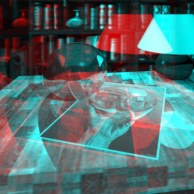
Or, create 3D images like this one for viewing
with red-blue glasses.
Extend the ray-tracer to create Single Image Random Dot Stereograms
(SIRDS). Here is a
paper on how to make them. Also check out this
page of examples.
Or, create 3D images like this one for viewing
with red-blue glasses.
![]()
![]()
![]()
![]() Implement a more realistic shading model. Credit will vary
depending on the sophistication of the model. A simple model factors
in the Fresnel term to compute the amount of light reflected and
transmitted at a perfect dielectric (e.g., glass). A more complex
model incorporates the notion of a microfacet distribution to broaden
the specular highlight. Accounting for the color dependence in the
Fresnel term permits a more metallic appearance. Even better, include
anisotropic reflections for a plane with parallel grains or a sphere
with grains that follow the lines of latitude or longitude. Sources:
Watt, Chapter 7, Foley et al, Section 16.7; Glassner, Chapter 4,
Section 4; Ward's SIGGRAPH '92 paper; Schlick's Eurographics Rendering
Workshop '93 paper.
Implement a more realistic shading model. Credit will vary
depending on the sophistication of the model. A simple model factors
in the Fresnel term to compute the amount of light reflected and
transmitted at a perfect dielectric (e.g., glass). A more complex
model incorporates the notion of a microfacet distribution to broaden
the specular highlight. Accounting for the color dependence in the
Fresnel term permits a more metallic appearance. Even better, include
anisotropic reflections for a plane with parallel grains or a sphere
with grains that follow the lines of latitude or longitude. Sources:
Watt, Chapter 7, Foley et al, Section 16.7; Glassner, Chapter 4,
Section 4; Ward's SIGGRAPH '92 paper; Schlick's Eurographics Rendering
Workshop '93 paper.
This all sounds kind of complex, and the physics behind it is. But the coding doesn't have to be. It can be worthwhile to look up one of these alternate models, since they do a much better job at surface shading. Be sure to demo the results in a way that makes the value added clear.
Theoretically, you could also invent new shading models. For instance, you could implement a less realistic model! Could you implement a shading model that produces something that looks like cel animation? Variable extra credit will be given for these "alternate" shading models. Links to ideas: Stylized Depictions
Note that you must still implement the Phong model.
![]()
![]()
![]()
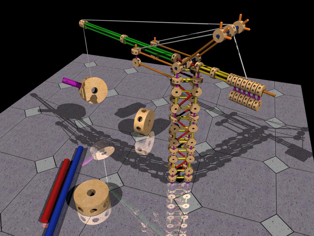
![]() Implement CSG, constructive solid geometry. This extension
allows you to create very interesting models. See page 108 of Glassner
for some implementation suggestions. An
excellent example of CSG was built by a grad student in the
University of Washington version of this graphics course.
Implement CSG, constructive solid geometry. This extension
allows you to create very interesting models. See page 108 of Glassner
for some implementation suggestions. An
excellent example of CSG was built by a grad student in the
University of Washington version of this graphics course.
![]()
![]()
![]()
![]() Add a particle systems simulation and renderer (Foley 20.5,
Watt 17.7).
Add a particle systems simulation and renderer (Foley 20.5,
Watt 17.7).
![]()
![]()
![]()
![]() Implement caustics. Caustics are variations in light intensity
caused by refractive focusing--everything from simple magnifying-glass
points to the shifting patterns on the bottom of a swimming pool.
An introduction, and a
paper
discussing a ray-trace project that included caustics.
Implement caustics. Caustics are variations in light intensity
caused by refractive focusing--everything from simple magnifying-glass
points to the shifting patterns on the bottom of a swimming pool.
An introduction, and a
paper
discussing a ray-trace project that included caustics.
You will need to use the "Canvas" system on the web to turn this program in. Once again, the artifact is a separate turnin from the code. As usual, if you developed your program on Windows or some other platform, you will need to port your work to the lab Linux machines before submitting it.
1) To turn in the main project, first clean your development area so that all *.o and binary executables are removed. Then follow submission directions on Canvas.
2) To turn in your artifact, you will need to submit at least two files: a) the image produced by the ray tracer and b) the scene file you used. You will also need to submit any resource files your scene requires, such as texture maps. Please submit your image as a jpg; you are free to name the remaining files however you wish.
If you wish to share additional information about the artifact (e.g the steps you used to create the image, artistic notes, etc.), feel free to include a readme.txt in your artifact submission.
Test code for running on linux machines.