Start LabView and open a new, blank VI. Tile the front panel
and block diagram displays.
Go to the Block Diagram window and right click to display
the Functions window. Pin the window so it will remain open.
In this lab you will using some functions and features of RoboLab
which is an extension of LabView built for programming Lego MindStorm
robots. We will not be programming for robots, simply using some of the
image capture and manipulation functions from RoboLab. To show the functions
for RoboLab click the Options icon on the Functions window.
(on Block Diagram)

On the Options window click on the arrow on the Palette View
box. From the list select LabView and ROBOLAB.
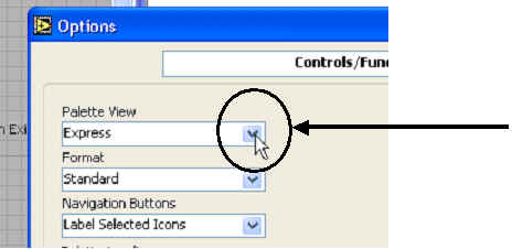
The function menu should now be similar to the picture in step 4.
Select the "MultiMedia" icon. The
"Multimedia" window should be displayed.
(on Block Diagram)
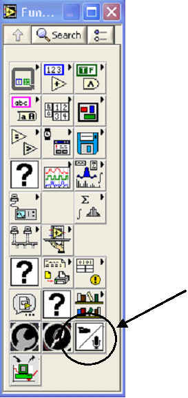
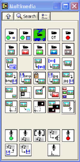
The steps for capturing and image from a web camera are:
-
open the camera (Init Large Image)
-
grab the image (Grab RGB)
-
convert the image to a picture (Convert to picture)
-
display the picture
-
close the camera (Close Camera)
The needed icons are circled below. Create and run the VI.
(on Block Diagram)
![]()
The only icon that is needed but not present on the Multimedia window is an
indicator to display the picture. To easily add an indicator go to the icon
on the "convert to picture" block diagram. Put the mouse over the
lower right terminal. When the wiring icon appears right click.
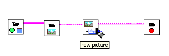
A menu pops up. Select Create -> Indicator. This
automatically adds an indicator and connects the wire to it.
Your diagram should now look like this:
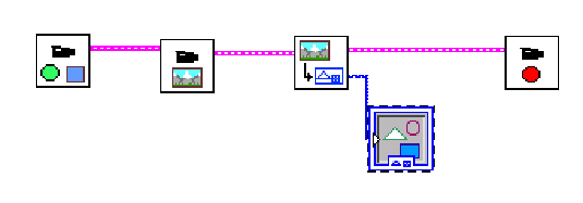
Run your program.
When selecting the camera click the check box with no explanation.
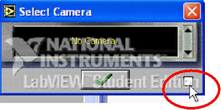
Click the icon with sliders that appears.
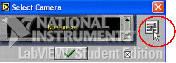
In the window that pops up ensure the brightness is not set to 0.
If the camera was attached correctly what was the nature
of the image that it captured. How is this different than say a digital
camera? What tools exist in labview that can give you greater control over
what image to capture and display?
Add the ability to view many images, not just one. Enclose
the Grab Image and Convert to Picture icons with a while loop.
The while loop function is on the Structures palette. If this
icon is not visible a the top level functions menu you will have to
switch the palette view back to Express as you did in step 3. After
adding the while loop change the Palette View back to LabView and
ROBOLAB.

Add the ability to save the chosen image to a file. Use the Save BMP
icon. This stands for save bitmap. Bitmap is a file
type for storing pictures.
(on Block Diagram)
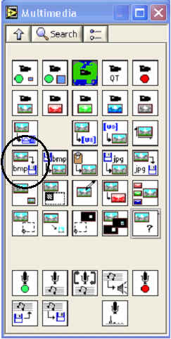
Add the ability to morph the picture. LabView includes a
control with several color scheme options. After adding your loop
and the ability to save images on exit, your VI block diagram should look
something like this:

Recall that when pictures are stored on computers they
are stored simply as numbers. A look up table is a list of numbers
corresponding to colors. Each original color has a resulting color. So each
pixel in a picture will have its original color replaced by some new color.
The lookup table is expecting a grayscale image, so first we need to
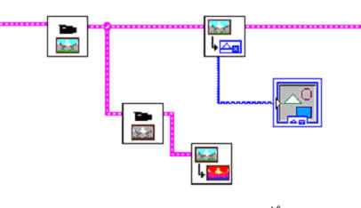
convert the color or RGB image to Grayscale. Place a Grab Grey icon
on your block diagram.
(on Block Diagram)
Now wire the output of the Grab RGB function to the
input of the Grab Grey function. Your block diagram should look
something like this:

Now we need to add the conversion to a new picture using a
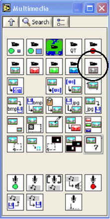
look up table. Select the Advanced Video icon from the Multimedia window:
(on Block Diagram)
![]()
After opening the Advanced Video window draw a Convert
Picture using LUT icon into the loop on your block diagram. LUT stands
for Look Up Table. We want to display the original picture and the resulting one so wire the
output of the Grab Grey function to the input of the convert picture icon.
(on Block Diagram)
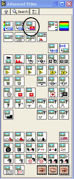
Wire the output of the Grab Grey function to the input of the
Convert Picture Using LUT icon.
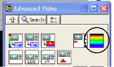
Insert a Lookup Table function to your block
diagram. It is the rainbow colored icon at the top right.
(on Block Diagram)
Wire the output of the Lookup Table to the lower left input of the Convert
Picture Using LUT
Add a control to the Lookup Table icon by right clicking the
terminal on the top left of the Lookup Table icon and select Create ->
Control.
Add another Convert to Picture icon to your block
diagram. You can either go back to the Multimedia window and add the
icon or click on the one in you block diagram and copy and paste it. Wire
the output of the Convert Picture Using LUT icon (the top right
terminal) to the Convert to Picture icon. Finally right click on the
output of the Convert to Picture icon to add an indicator. Your block
diagram should now look something like this:

Add the ability to choose whether to save the picture or
not. Change the title of the stop button to Quit instead of Save
Picture. On the front panel select the Boolean controls icon. On
the Boolean controls window select the Vertical Toggle Switch.
Change the title of this switch to Put Switch Up To Save Picture On Exit
or something similar.
(on Front Panel)

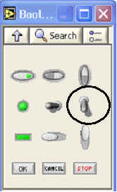
Notice on the block diagram the icon for the toggle switch.
The toggle switch has an input of true or false. If the switch
is down the output is false. If the switch is up it is true. Be sure on the
block diagram that the switch is inside the while loop. Rewire the Save
BMP and Close Camera icons so that the wire splits off to these
two icons instead of them being in a series.
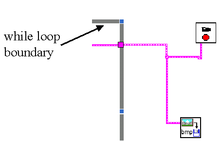
Now add a Case Structure around the Save BMP icon. The Case
structure is on the Structure Menu. (You have to alter the palette view
from Robolab and LAbView back to Express to see the structures
menu.)
(on Block Diagram)

The Case structure is similar to the While loop. When you place it on the
block diagram you must drag it around the icons you want it to control. The
only icon to put inside the Case box is the Save BMP icon.
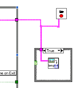
Notice the arrows at the top of the case structure. Initially the label at
the top says true. Click the arrows at the top and the label should
change to false and the Save BMP icon should disappear. This
means if the input to the Case structure is true the image will be saved to
a file, but if the input is false nothing will happen. The ability to have
programs make decisions based on input and values is a very powerful and
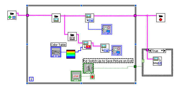
necessary tool in building programs. The input to the Case structure should
be the output of the toggle switch. Wire the output of the toggle switch to
the input of the case structure. Your block diagram should now look
something like this:
What next? One interesting change would be to alter one of the lookup tables or add your own.